
电子说
1 测试环境
开发板:N32L40XCL-STB V1.0
开发环境:RT-Thread studio 2.2.6
RT-Thread版本:4.0.2
2 硬件资源介绍
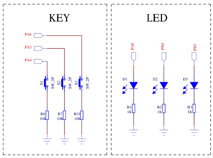
开发板上共有3个按键和3个LED如下图所示。
GPIO输入输出测试:KEY1对应引脚设置为GPIO输入,控制LED1、LED2亮灭
GPIO中断模式测试:KEY2对应引脚设置为下降沿触发,触发后打印KEY2!等若干字符
LED3指示系统正常工作

3 GPIO测试代码
关于工程创建等可参考其他人的文章,在applications文件夹中创建gpio_test.c文件并加入如下的测试代码
#include
#include
#include
/* defined the LED1 pin: PA8 /
#define LED1_PIN GET_PIN(A, 8)
/ defined the LED2 pin: PB4 /
#define LED2_PIN GET_PIN(B, 4)
/ defined the KEY1 pin: PA4 /
#define KEY1_PIN GET_PIN(A, 4)
/ defined the KEY2 pin: PA5 */
#define KEY2_PIN GET_PIN(A, 5)
static uint8_t curr_st = 0;
static uint8_t next_st = 0;
static uint8_t led_st = 0;
static void key_led_thread_entry(void parameter)
{
while (1) {
/ led status switch /
if (rt_pin_read(KEY1_PIN) == PIN_LOW) {
rt_thread_mdelay(20);
if (rt_pin_read(KEY1_PIN) == PIN_LOW) {
next_st = 1;
} else {
next_st = 0;
}
} else {
next_st = 0;
}
/ switch on/off the led */
if ((curr_st == 0) && (next_st != 0)) {
led_st = !led_st;
} else {
led_st = led_st;
}
curr_st = next_st;
if (led_st) {
rt_pin_write(LED1_PIN, PIN_HIGH);
rt_pin_write(LED2_PIN, PIN_LOW);
} else {
rt_pin_write(LED1_PIN, PIN_LOW);
rt_pin_write(LED2_PIN, PIN_HIGH);
}
rt_thread_mdelay(20);
}
}
static void key2_callback(void *args)
{
char str = args;
rt_kprintf(str);
}
int gpio_test(void)
{
/ gpio input and output test /
rt_pin_mode(KEY1_PIN, PIN_MODE_INPUT_PULLUP);
rt_pin_mode(LED1_PIN, PIN_MODE_OUTPUT);
rt_pin_write(LED1_PIN, PIN_LOW);
rt_pin_mode(LED2_PIN, PIN_MODE_OUTPUT);
rt_pin_write(LED2_PIN, PIN_HIGH);
rt_thread_t tid;
tid = rt_thread_create("key_led", key_led_thread_entry, RT_NULL, 512, 10, 5);
if (tid != RT_NULL) {
rt_thread_startup(tid);
} else {
rt_kprintf("startup the thread failed!n");
}
/ gpio irq test */
rt_pin_mode(KEY2_PIN, PIN_MODE_INPUT_PULLUP);
rt_pin_attach_irq(KEY2_PIN, PIN_IRQ_MODE_FALLING, key2_callback, (void *)"KEY2!n");
rt_pin_irq_enable(KEY2_PIN, PIN_IRQ_ENABLE);
}
INIT_APP_EXPORT(gpio_test);
全部0条评论

快来发表一下你的评论吧 !
